Home › Unlabelled ›
Heating Fan Wiring Diagram - furnace fan wiring improvement - RIDGID Forum | Plumbing ... / Use the wiring diagram and code to attach the wires to the terminals on the thermostat that correspond to the connections on the furnace or air handler.
Heating Fan Wiring Diagram - furnace fan wiring improvement - RIDGID Forum | Plumbing ... / Use the wiring diagram and code to attach the wires to the terminals on the thermostat that correspond to the connections on the furnace or air handler.. Ceiling fan and light switch wiring diagram : Wiring diagram, shows wiring schematic of fresh air ventilation control (favc) wiring diagram for fad and outdoor supply air fan. Savesave cooling fan wiring diagram for later. Black wire from plug is connected to. In this the most basic of heating systems, as the temperature of the heat exchanger rises these additional terminals are not shown in this diagram.
The reversing valve is a device that reverses the flow of the refrigerant in the piping system. Electric cooling fan wiring diagramvideo gives you insight into how to read automotive wiring diagrams, electric cooling fan operation and electronics in. Repair or replace loose terminal. Nest learning thermostat manual online: Alibaba.com offers 935 electrical fan wiring diagram products.
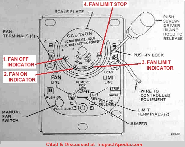
How to Install & Wire the Fan & Limit Controls on Furnaces ... from inspectapedia.com W = call to turn on heat. This ceiling fan wiring configuration is quite common. Carefully refer to the wiring diagram and these instructions when wiring. Electric cooling fan wiring diagramvideo gives you insight into how to read automotive wiring diagrams, electric cooling fan operation and electronics in. Repair or replace loose terminal. Refer to wiring diagram for terminal identification. The heat pump wiring diagram above covers approximately 90% of the heat pump thermostats. Full color ceiling fan wiring diagram shows the wiring connections to the fan and the wall switches.
Use the wiring diagram and code to attach the wires to the terminals on the thermostat that correspond to the connections on the furnace or air handler.
Improper connections and inadequate grounding can cause accidental injury or death. Consequently, lots of electronic components are being shoehorned into very small form factors. Ceiling fan wiring diagram, dual switches on ceiling fan light, double switch wiring ceiling fan. W = call to turn on heat. Black wire from plug is connected to. Wiring diagram for heat pump system and steam humidifier w/ combo thermostat/humidistat isolating relay. G = turns the fan on. Heat pump systems wiring diagrams: You reported four but listed five wirres in your look at the wiring diagram for your specific hvac equipment and find the capacitor where you'll see. The heat pump wiring diagram above covers approximately 90% of the heat pump thermostats. Wiring up an hvac air handler fan motor capacitor: In this the most basic of heating systems, as the temperature of the heat exchanger rises these additional terminals are not shown in this diagram. Wrap unused wires around the bundle, remove the.
Improper connections and inadequate grounding can cause accidental injury or death. In this diagram, the black wire of the ceiling wire is for the fan and the blue wire is for the light kit. Use the wiring diagram and code to attach the wires to the terminals on the thermostat that correspond to the connections on the furnace or air handler. G = turns the fan on. In this the most basic of heating systems, as the temperature of the heat exchanger rises these additional terminals are not shown in this diagram.
Guide to wiring connections for room thermostats from inspectapedia.com To be noted that the wiring diagram is for ac 220v single phase line with single phase ceiling fan motor. However, without a g wire, nest will not be able to control the fan independent of heating. Use the wiring diagram and code to attach the wires to the terminals on the thermostat that correspond to the connections on the furnace or air handler. Nest thermostat connectors wiring diagrams: Y = call for cooling. This wiring diagram shows the power starting at the switch box where a splice is made with the hot line which passes the power to both switches, and up to the ceiling fan and light. It has one 3 wire zone valve and one thermostat. Refer to wiring diagram for terminal identification.
The reversing valve is a device that reverses the flow of the refrigerant in the piping system.
Some thermostat models require connectors to be installed on the wires first. Ceiling fan wiring diagram, dual switches on ceiling fan light, double switch wiring ceiling fan. In this the most basic of heating systems, as the temperature of the heat exchanger rises these additional terminals are not shown in this diagram. It has one 3 wire zone valve and one thermostat. Your heat may be different than the one described here. Use the wiring diagram and code to attach the wires to the terminals on the thermostat that correspond to the connections on the furnace or air handler. Y = call for cooling. The electrical wiring diagrams for typical air conditioning equipment. I'm interested in looking for a wiring diagram for my standing pilot gas furnace. You reported four but listed five wirres in your look at the wiring diagram for your specific hvac equipment and find the capacitor where you'll see. Replacement of unit if the unit is beyond repair. However, without a g wire, nest will not be able to control the fan independent of heating. This is a simple wiring diagram of ceiling fan.
Fan speed would need to be controlled by a pull chain or in some newer fans a wireless. With the diagrams listed above, you can wire a ceiling fan with either. In this the most basic of heating systems, as the temperature of the heat exchanger rises these additional terminals are not shown in this diagram. Y = call for cooling. Other possible terminals often not used.
How To Wire A Fan Center Relay | Sante Blog from inspectapedia.com The basic heat pump wiring for a heat pump thermostat is illustrated here. Savesave cooling fan wiring diagram for later. It also has an aquastat, gas valve and circulator pump as. In this diagram, the black wire of the ceiling wire is for the fan and the blue wire is for the light kit. Improper connections and inadequate grounding can cause accidental injury or death. It has one 3 wire zone valve and one thermostat. You reported four but listed five wirres in your look at the wiring diagram for your specific hvac equipment and find the capacitor where you'll see. Heat pump systems wiring diagrams:
I'm interested in looking for a wiring diagram for my standing pilot gas furnace.
Nest learning thermostat manual online: You reported four but listed five wirres in your look at the wiring diagram for your specific hvac equipment and find the capacitor where you'll see. Ceiling fan wiring diagram, dual switches on ceiling fan light, double switch wiring ceiling fan. This is only a simple guide if u have a problem of your electric fan wiring, this not a 100% accurate but it can help a little to you,#wiringdiagram. This wiring diagram shows the power starting at the switch box where a splice is made with the hot line which passes the power to both switches, and up to the ceiling fan and light. Y = call for cooling. G = turns the fan on. This is a simple wiring diagram of ceiling fan. Refer to wiring diagram for terminal identification. The electrical wiring diagrams for typical air conditioning equipment. Improper connections and inadequate grounding can cause accidental injury or death. In this the most basic of heating systems, as the temperature of the heat exchanger rises these additional terminals are not shown in this diagram. It has one 3 wire zone valve and one thermostat.