Trailer Brake Wiring Diagram 7 Way / 7 Way Wiring Diagram Trailer Brakes | Trailer Wiring Diagram - It is an orange wire.. Each component ought to be set and connected with other parts in specific way. Basically, this is a way of applying the trailer brakes if the the trailer wiring diagram shows this wire going to all the lights and brakes. A 4 pin connector is almost always used on trailers that do not utilize electric trailer brakes nor have any need for accessory power and therefore the trailer only requires power for lights. Mksap11 also posted this pic while i could be wrong but i have a feeling splicing the wires will probably through a light on the dash. 7 way plug wiring diagram standard wiring* post purpose wire color tm park light green (+) battery feed black rt right turn/brake light brown lt left turn/brake light red s trailer electric brakes blue gd ground white a accessory yellow this is the most common (standard).
Mksap11 also posted this pic while i could be wrong but i have a feeling splicing the wires will probably through a light on the dash. This brake controller wiring diagram shows which wire goes where. Use these tips to fix common trailer wiring issues on the go and get your trailer on the road. What if your brake lights it's crucial to diagnose a trailer wiring problem early on to get you back on the road in the safest way. To purchase this product and other towing accessories visit.
Trailer Breakaway Wiring Schematic | Free Wiring Diagram from ricardolevinsmorales.com Use these tips to fix common trailer wiring issues on the go and get your trailer on the road. This brake controller wiring diagram shows which wire goes where. Pinout diagrams, minimum wire sizes, and common wire colors for 4 pin, 6 pin, and 7 pin truck/trailer connectors. Our trailer wiring diagram is a colour coded guide designed to help you wire your trailer plug or socket. Many trailers are required to have a breakaway system on board. Whoever put the trailer wiring on either cross wired something or a wire got pinched somewhere. Offroaders staff editor trailer & towing. Each component ought to be set and connected with other parts in specific way.
Some may be made that way but the ones i've pulled are better.
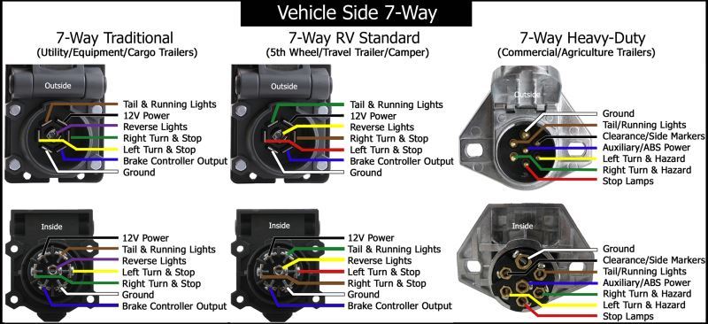
What if your brake lights it's crucial to diagnose a trailer wiring problem early on to get you back on the road in the safest way. This brake controller wiring diagram shows which wire goes where. 12n (normal) electrics wiring diagram for the exterior lighting on a trailer or caravan from western towing. Whoever put the trailer wiring on either cross wired something or a wire got pinched somewhere. Each component ought to be set and connected with other parts in specific way. The diagram below shows the view from outside the vehicle socket (under the flap) and from inside. I do not have the electric trailer brakes but do have the control module/unit. But what happens when you start experiencing trailer light wiring problems? A number of standards prevail in north america, or parts of it, for trailer connectors, the electrical connectors between vehicles and the trailers they tow that provide a means of control for the trailers. ✔ bougerv trailer wire provides a fast, simple way to connect the wires from. Not sure which wires attach to what on your trailer connectors? The brake lights come off the f15 10amp fuse in the main fuse block on my 05ml. There are two ways to do trailer brake wiring, the right way and the wrong way.
The trailer wiring diagrams listed below, should help identify any wiring issues you may have with your trailer. A number of standards prevail in north america, or parts of it, for trailer connectors, the electrical connectors between vehicles and the trailers they tow that provide a means of control for the trailers. Many trailers are required to have a breakaway system on board. Pinout diagrams, minimum wire sizes, and common wire colors for 4 pin, 6 pin, and 7 pin truck/trailer connectors. It is an orange wire.
Wiring Diagrams for 7-way Round and 7-Way Blade Connectors ... from www.etrailer.com The diagram below shows the proper way to wire the connector to your trailer or vehicle. The following page contains information about trailer to vehicle wiring diagrams including: Not sure which wires attach to what on your trailer connectors? Basically, this is a way of applying the trailer brakes if the the trailer wiring diagram shows this wire going to all the lights and brakes. 7 wire trailer circuit, 6 wire trailer circuit, 4 wire trailer circuit and other trailer wiring diagrams. Travel trailers don't have separate brake battery. Or why not make your diy installation easier ebs (electronic brake system) connectors are used for the electrical connection of the abs/ebs braking systems between the truck and trailer for. For a cap 3rd brake light, you i'm looking to get oem 7 pin and 4 way flat to work.
The diagram below shows the proper way to wire the connector to your trailer or vehicle.
I do not have the electric trailer brakes but do have the control module/unit. It is an orange wire. Whoever put the trailer wiring on either cross wired something or a wire got pinched somewhere. Getting back to the dodge caravan… it didn't come with the factory tow package, so i this is simply a way to work around some of today's load sensitive cars that can't handle the added electrical draw that trailer hookups require. Doing your trailer wiring this way will cost a bit more than the ready made kits, and takes a bunch more time to install, but in the long run pin 7 is always hot on abs equipped trailers with air brakes; Use these tips to fix common trailer wiring issues on the go and get your trailer on the road. Or why not make your diy installation easier ebs (electronic brake system) connectors are used for the electrical connection of the abs/ebs braking systems between the truck and trailer for. The diagram below shows the proper way to wire the connector to your trailer or vehicle. Uneven braking occurs when the length of the wire between each of the magnet connections adds resistance and therefore electric brake wiring: Find the trailer light wiring diagram below that corresponds to your existing configuration. A brake controller has only one output wire. Please follow bougerv trailer wiring diagram in description or manual. 7 way plug wiring diagram standard wiring* post purpose wire color tm park light green (+) battery feed black rt right turn/brake light brown lt left turn/brake light red s trailer electric brakes blue gd ground white a accessory yellow this is the most common (standard).
To purchase this product and other towing accessories visit. As the name implies, they use four wires to carry out the vital lighting functions. 1 way trailer brakes can get you killed.if you are going down a long steep grade (hill) your car/truck brakes (which are only made to stop your car or truck) will get hot and glaze over and eventually. Offroaders staff editor trailer & towing. Pinout diagrams, minimum wire sizes, and common wire colors for 4 pin, 6 pin, and 7 pin truck/trailer connectors.
Wiring Diagram for Utility Trailer with Electric Brakes ... from wholefoodsonabudget.com Otherwise, the arrangement won't work… This requires a switch to go from one. Pinout diagrams, minimum wire sizes, and common wire colors for 4 pin, 6 pin, and 7 pin truck/trailer connectors. A number of standards prevail in north america, or parts of it, for trailer connectors, the electrical connectors between vehicles and the trailers they tow that provide a means of control for the trailers. Trailer plug wiring is standardized across all vehicles, no point trying to find vehicle specific info. The thing is i have to go to the tail lights to. 7 wire trailer circuit, 6 wire trailer circuit, 4 wire trailer circuit and other trailer wiring diagrams. Offroaders staff editor trailer & towing.
Trailer plug wiring is standardized across all vehicles, no point trying to find vehicle specific info.
Not sure which wires attach to what on your trailer connectors? 7 wire trailer circuit, 6 wire trailer circuit, 4 wire trailer circuit and other trailer wiring diagrams. 12n (normal) electrics wiring diagram for the exterior lighting on a trailer or caravan from western towing. This is for the trailer only. Offroaders staff editor trailer & towing. Trailer plug wiring is standardized across all vehicles, no point trying to find vehicle specific info. Please follow bougerv trailer wiring diagram in description or manual. The diagram below shows the proper way to wire the connector to your trailer or vehicle. Some may be made that way but the ones i've pulled are better. This requires a switch to go from one. I do not have the electric trailer brakes but do have the control module/unit. I use it for the electric brake controller on non air brake trailers. The following page contains information about trailer to vehicle wiring diagrams including: